Indoor-Outdoor
Indoor-Outdoor
Overview
The following sections describe on-going research within the Communications Group with regard to the study of wideband channels associated with the indoor-outdoor and indoor-indoor environments.
VNA Measurement System
The measurement system was based upon the classic vector network analyzer (VNA) technique. The VNA is used to measure the forward transmission scattering coefficient, S21(effectively the complex channel frequency response). The channel impulse response is obtained by inverse Fourier transforming the frequency domain data. The multipath resolution in the delay domain is inversely proportional to the swept bandwidth, such that tres =2.2/Bsweep, where Bsweep denotes the swept bandwidth and the factor of 2.2 accounts for the mainlobe spreading due to windowing (in the results shown on the web-pages a 3 term Blackmann-Harris window was employed unless otherwise stated). The Fourier transform repeat range is given by KNpts/Bsweep where K<1 to account for spurious responses in the latter part of the delay profile due to calibration instability.
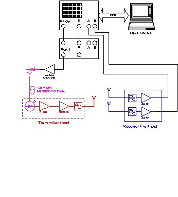
In order to obtain useful transmit-receive separations, the transmitter was remoted from the receiver and VNA by means of a 100 m military specified multimode fibre optic link. In order to increase the flexibility of the measurement system, both the A and B channels of an HP8753C VNA were utilised. This allowed measurements on two receive antenna to be made simultaneously. A diagramatic representation of the measurement system is shown below.

A swept frequency signal from Port 1 of the test set is used to drive the FO link. After wideband photodetection at the transmitter head end, the signal is amplified and then injected into the channel.
At the receive antennas, the signal is filtered using in-house designed RF bandpass filters (optimised for low insertion loss and the rejection of image and spurious frequencies) and then amplified prior to being fed to the VNA "A" and "B" input ports.
All measurements and data capture are automated using a laptop PC with control via HPIB.
Note: the S-parameter test set Port 1 output is used such that the frequency doubler can be utilised for measurements in the 5 GHz range. (The HP8753C has a source capability to 3 GHz, whilst the receiver section operates to 6 GHz).
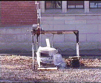
In addition to obtaining channel impulse responses for post-processing analysis, channel modelling and inclusion in a propagation database, the system can also be used to obtain the multipath angle of arrival (AoA). This is achieved by means of constructing a synthetic volume aperture, which in this case consists of a large X-Y positioner (1.5mx1.5m) under stepper motor control. Channel impulse responses are obtained from a rectangular grid. The delay domain signal is time gated around each of the multipath signals and a 2-D Fourier Transform technique used to identify the angle of arrival of the transmitted signal as a function of delay.
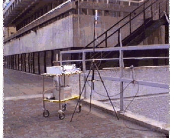
Such a measurement technique is extremely useful in identifying propagation mechansims, supporting the development of new EM prediction theory and the validation of propagation modelling tools. Pictures of the transmitter and receiver are shown below, including the X-Y positioner.


